Help Previous Page Up a Level Next Page Attachments   Jerome's Sunbeam Pages
5 Ws and an H Links Guides Tomato Gallery Document Revision Log  5.12.1. Electrical Schematics


Guides
Index
Cooling System Engine Fuel System Clutch & Propeller Shaft Gearbox & Overdrive Front Suspension Rear Axle Rear Suspension
Steering Brakes Wheels and Tyres Electrical System Body Lubrication Oil Seals and Bearings Heating & Ventilation Special Tools
Electrical Schematics Devices: As Designed Wire/Device Concordance


Series II Wiring Diagram - Colour -600- 100%
Series II Wiring Diagram - Colour
From Tigers East/Alpines East
Note: multi-colour wires are labelled as BaseStripe, unlike other diagrams that use Stripe/Base. RW is W/R, for example.
     
Series II Wiring Diagram - Monochrome -600- 100%
Series II Wiring Diagram - Monochrome
From a collection of Supplements to "Motor Trader," 25 July 1962. Labels and legends were added to the diagram in the SII Owner's Handbook. Book from the public library; a copy of the original article from Jürgen Morche.
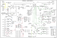
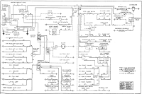
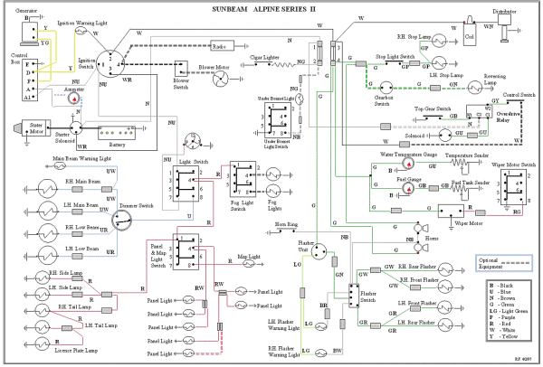
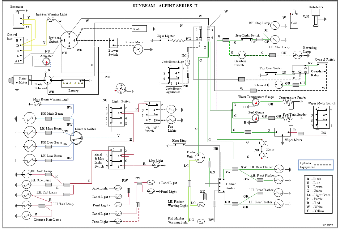
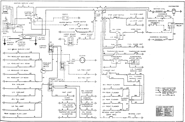
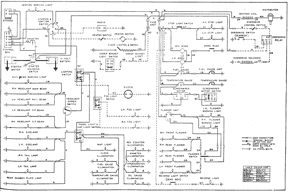
      The schematics assume a RHD car. This can be seen in the signal flasher lights, which appear to be labelled wrong. The two diagrams differ slightly in the wiring assigned to the wiper motor; otherwise they are equivalent.

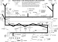
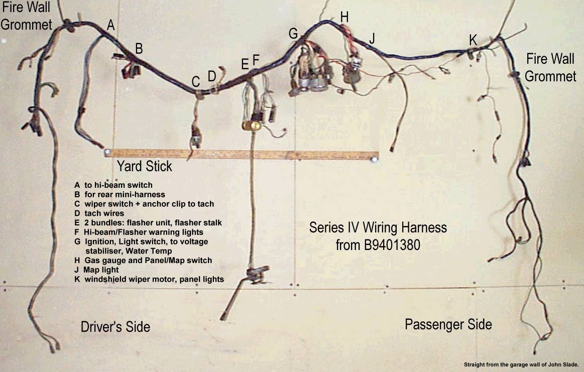
In Situ Harness Schematic


In Situ Series II Wiring Harness Schematic -600- 100%
In Situ Series II Wiring Harness Schematic
From the Tomato
      This is what my harness looks like, laid out schematically as it would be in the car when viewed from inside, matched to the schematics above. Line thickness roughly indicates bundle thickness, but length is arbitrary (though there are segment lengths). The bend on the lower right was how I found the harness, and demonstrates that it's just a RHD harness bent back on itself half-way across the span of the car, just upstream of the Fuel Gauge (or Lighter). The harness passes through a single hole in the firewall, adding to the lumpage (and confusion).*

There is a Red wire at the inside end of the harness for the Wiper Motor that I have moved to the motor.


There are several devices affected by the mirrored dash and bend.
  • The Fuel and Water gauges must be crossed, easy to do since they're at the bend.
  • The Light and Panel/Map switches must be crossed, also quite easy to do.
  • Turn-signal warning lamps must be crossed. More of a hassle since they're wide gauges (terminals further apart) at the end of the harness.
  • The hi-beam switch is a half-dash-width away from its indicator lamp, and needs an extension.
  • The Wiper Motor is now at the opposite end of the car from its switch and power line, and needs an extension.

The OD circuit is mostly a guess based on schematics and the location of the larger components. Grey bits indicate things in their current (not ideal) state. Dotted lines indicate wiring for options, delivered as additional mini-harnesses. I will be incorporating them into the harness. Tell Me what else you know.
*In later Series the harness is U-shaped and passes through the firewall at both ends. John Slade provided a Series IV harness for comparison.

Electrical Schematics Devices: As Designed Wire/Device Concordance
Guides
Index
Cooling System Engine Fuel System Clutch & Propeller Shaft Gearbox & Overdrive Front Suspension Rear Axle Rear Suspension
Steering Brakes Wheels and Tyres Electrical System Body Lubrication Oil Seals and Bearings Heating & Ventilation Special Tools

Help Previous Page Up a Level Next Page Attachments   5.12.1. Electrical Schematics
JOY/CVP/YSEV/0.31 - November 7, 1999